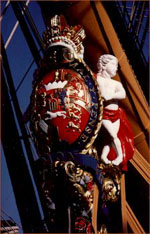
HMS Victory
from Scratch
updated March 20, 2014 10:35 AM
(Jump to latest update at end of page)
Jump to method I used to create the 1:48 scaled plans
using the plans in:
| John McKay's The 100-Gun Ship Victory, | |
| C. Nepean Longridge's The Anatomy of Nelson's Ships, | |
| Alan McGowan's HMS Victory, drawings by McKay. | |
| Peter Goodwin's English Man of War 1650~1850. |
It is also my intention to fashion every piece of timber used in the original construction. Tree nails will be used in the fabrication instead of iron and copper nails until we get to the copper plating of the bottom. Because of the myriad of timbers used in constructing the frames, this project will probably take several years, and may well end up with just the frame, including beams, knees, carlins, et al.
The scale I have selected is 1:48, or 1/4" = 1 foot. This makes a rather large vessel, but allows adding the copious detail that is included in McKay's drawings. I started at 1:75, got through the stern and stem including all the deadwood, but quickly got the idea of how difficult it would be to work with the detailed timbers at that scale. I'm much more comfortable at the larger scale, even though it meant starting over.
I find that I already have the equipment to enlarge all of the plans to the 1/4" scale. My scanner, Adobe PS Elements software and my Compaq printer provide an exact 1/4" scale set of plans from the McKay drawings, which were published at 1:192. My first effort is to recreate the stern post and deadwood, a partial keel and the stem and deadwood. The rest of the keel will be left until a few frames have been built and must be installed on the keel. The first and last flat frames will be installed first. The stem and stern will be shored up to the proper vertical position on the construction board, with the stern about a scale foot below the stem keel, and the rest of the keel timbers will be installed.
Since this is a model that will end up being almost five feet long, I am going to build the stern and stem framing completely before attacking the center of the hull. That way, I can work with sections that are more manageable instead of swinging around the whole thing.
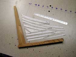
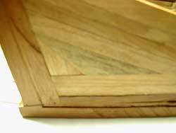
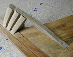
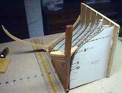
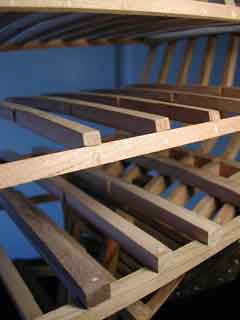
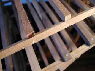
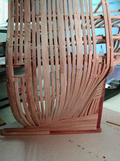
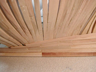
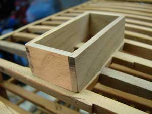
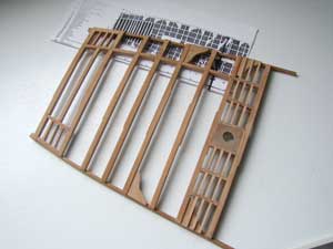
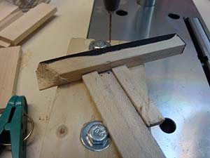
These
images will serve to show the size of the stern post, relative to the
six inch rule shown.
The
left image shows the stern post, inner post and the rear-most timber of
the keel already constructed and assembled, complete with rabbets and
that portion of the area above the bearding line that lies on the inner
post. The patterns for the deadwood are cut ready to cut out the
timbers.
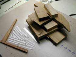
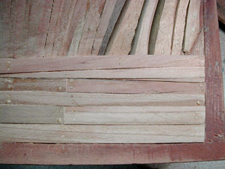
The
right image just illustrates the scraps of cherry wood that I will be
using to construct the Victory frame. I'll be able to get all of
the deadwood, both stern and stem out of this amount of scrap, for which
I paid $1/pound.
These images show the assembled stern post, first segment of keel and all the deadwood for the stern, including the first segment of keelson.To the right, a somewhat blurred image of the individual segments of the deadwood, each timber cut to match the McKay drawing shown in other images.
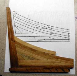
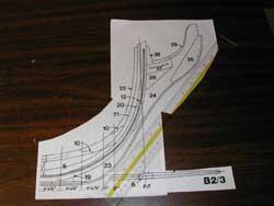
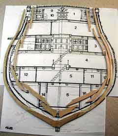
This
image shows the stem blown up to the proper 1/4" scale, ready to
be cut into pattern pieces, as done for the stern above.
My
intention is to recreate the Victory as faithfully as I can, and the most
challenging task will be to do the frames, one futtock at a time, with
each station pair faired together for strength.
Next
comes the task of installing the Transoms. There is some conflict
between the Water Lines of McGowan's book and the Transoms pictured in
McKay's own book. You may notice that I opted to go with the images
of the Transoms, except for number 4, which is not compatible with all
the rest. Number 4 will have to be created by averaging between
3 and 5.
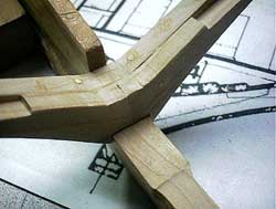
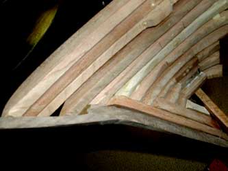
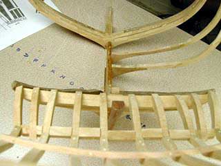
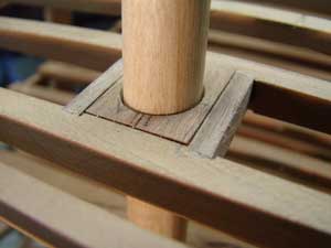
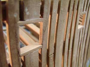
The
left image shows the first three Transoms installed using trunnels (tree-nails). Each Transom is made up of three pieces of timber, better seen in the
close-up image to the right.
Note
that the Transoms have not been beveled. That is to be accomplished
after installation and after the first Fashion pieces have been installed.
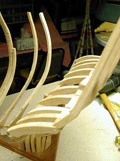
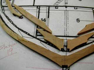
So,
we have the first set of Transoms installed, and now we move to the first
of the Fashion pieces that must provide the proper hull curvature from
the stern deadwood to the transoms. Using station 31 and 32 as guides,
the profile of the Fashion piece 141, from McKays book, is roughly determined.
This first cut is rough in the sense that any corrections that most probably
will be found necessary will be performed and the piece re-cut. This Fashion piece 141 intersects all three of these first Transoms and
will provide the hull template for the succeeding pieces.
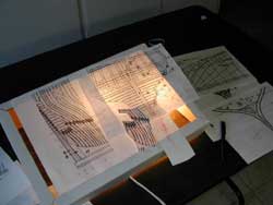
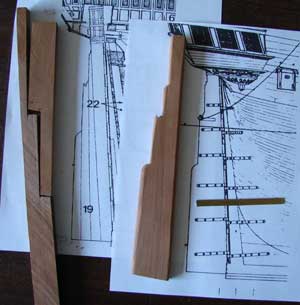
The
left image shows some of the extensive work that must be done to determine
the shape of the fashion piece, if it is to duplicate the timbers used
in the original ship. On the right, the blank is ready to saw out
to provide the complex curvature of the Fashion piece 141.
Doing the Victory from scratch is an interesting project, but doing it so as to replicate the original construction is very much more a task.
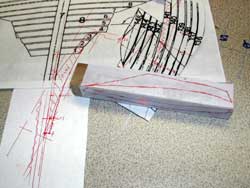
I
finally decided that I MUST prepare all the templates for Water Lines
and Body Plans, along with the last square frame set before I could get
the proper contour into the Fashion Pieces that I had started. So,
here is the lower half of the Station 21 pair of frames. I don't
want to go on up higher right now, but I cut the futtocks and have them
set aside.
The
pair of frames, each 15 inches wide at the keel, make quite a distinguished
set of timbers. Naturally, each member of the pair has to have offset
scarphs at the futtock joints, and here comes the importance of some of
the other books in my library. McGowan's is particularly useful
in this regard, as it shows several of the often used methods of futtock
construction in those days.
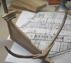
Now, the template is ready to help design the curvature of the fashion pieces, as I add them to fill in as I add Transoms.
Seems to work just fine as can be seen in the image to the right, where the stern piece of the Victory is up against the template. The first fashion piece can be seen. and the template allows me to finish the fashion pieces to the exact water lines.
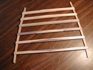
The rest of the Transoms have now been constructed using various hardwoods. This image shows numbers 6 through 11, the Wing Transom.
And this is what they look like after being mounted to the Inner Stern Post. They still require beveling and it appears that one or two may have to be slightly modified in order to allow the cant frames to make proper contact.
Now,
let's look at the Cant Frames and some of the Fashion Pieces done on the
starboard side of the stern post. From here on forward to the first
square frame, station 21, the cant frames will still be secured to the
deadwood and become less angled to the keel.
These
first cant frames are at 45 degree and will gradually change to 90 degrees
when they meet station 21 full frame.
Needless to say, I got into a lot of trouble when attempting to determine the shape of cant frames above the waterlines provided in the plans. I decided that I again would have to back off of the cant frames and install the counter timbers and stern timbers so that I could put in the various decks enough to determine the shape of the frames aft of station 21.
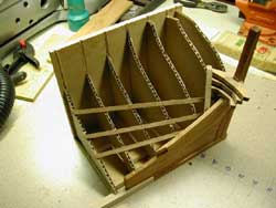
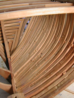
This image shows the counter timbers mounted upon the top of the wing transom, otherwise known as transom number 11!
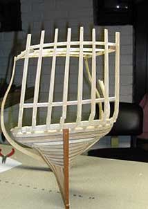
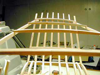
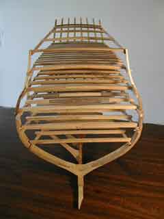
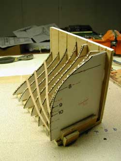
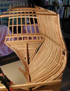
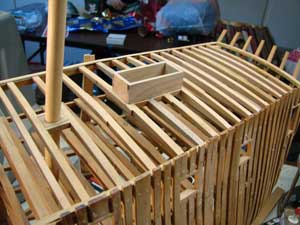
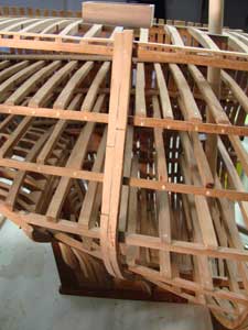
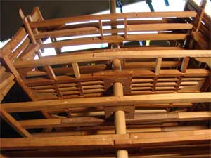
This 'head-on' view shows all six decks in place, pinned with trunnels to the station 21 sister frames and in the aft to the transoms and counter timbers as necessary.
All but the poop deck are removable, as they must be equipped with the zillion carlins yet to be created. I could now go ahead and do the cant frames, or I could continue with decking frame-up. I'm not yet sure which I will do.
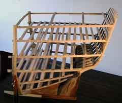
This view from the larboard shows all the decks in place, and show the deck shelves extending on past station 21 for scarphing to the mid-section shelves when I get to that part.
The aft end from station 21 has worked out quite well, as it contains all of the poop deck and all the carlins surrounding the mizzen mast, together with it's step on the keelson. That will come soon.
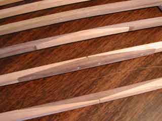
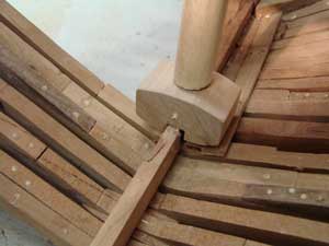
These detail shots just show the trunnels used to secure the beams to the shelving. Lots of woodwork used in these tall ships!
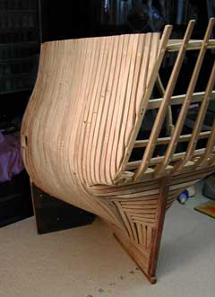
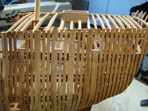
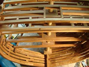
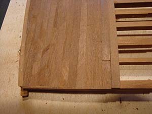
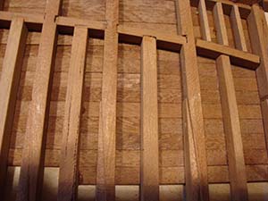
This view shows the lowest futtock of each frame snugged together at the keel. None of the smoothing and sanding has yet been done, so everything looks like a work in progress.
I have installed the waterway for the middle deck permanently even though the deck shelf and beams are removable. This was done to provide an intermediate secure fastening of each frame to lock each one in place.
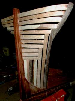
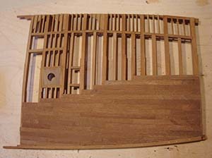
This image showing the inside of all the frames on the port side of the stern also shows the one waterway that was installed to act as a mid-frame support for all the cant frames. This waterway is for the Middle Deck and is fashioned from walnut to add a measure of stiffness to the curve of the hull while the frames were all installed. Each frame is trunneled to the waterway. Note that all the decks have been removed for these images.
The frames have been cut off at the top to match the line of the 1805 Victory, where the poop deck actually rises above the bulwarks at the forward end of the deck.
Updated January 21, 2007
A long period of time has expired since updating this page, so there will be some new features included.
Note that the Captain's convenience door to access the side closets in his living quarters has been added to the starboard side.
I believe that I will apply some decking to the Poop deck, perhaps along the starboard side and under the taffrail so as to allow installation of the transom knees supporting the taffrail and flag lockers.
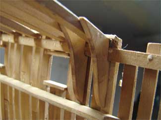
However, prior to that, I have installed three of the Hanging Knees on the Poop deck beams. Two are shown to the left, at the Station 21 site. The Quarterdeck has been removed in this image, to allow free access to the area for mounting the knees.
Now, I am putting in all the carlins required to support the Upper Deck with its load of 12 pounder long guns. Lodging knees go in first, followed by the heavy carlins immediately under the gun sites. Lighter carlins are then added.
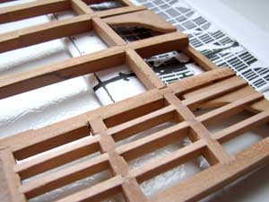
These carlins are cut so as to overlap the lodging knee in this space. It is not clear from the McKay drawings whether or not this really occurs. They may just terminate at the knee, but I can always cut them shorter.
This image shows the entire aft end of the Upper gun deck, from the Mizzen mast back. The carlins on either side of the mast are in and complete, the heavier carlins on the port side are in and the carlins under the guns are started. No hanging knees are in place yet, but they will be added after the deck is otherwise complete. I have to be careful about hanging knees, as the deck must be 'portable', and removable to work on.
Here is a view of all the decks looking down from the upper deck. Note that all of them now have the collar around the Mizzen mast. I have also located hanging knees on each level so as to afix the vertical location of each deck. This eliminates the need for nails to fix each of the decks in location.
The pintles and gudgeons are made of brass, with the selection of tubing and rod to allow smooth insertion of the one into the other. Ordinary low-temperature solder is used to attach the tubing and rods to the brass strips which have been shaped from wider brass strip purchased at the local hardware.
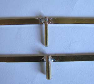
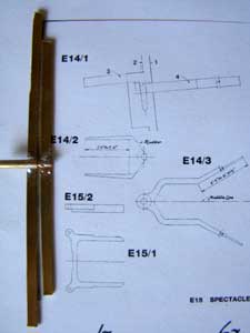
The McKay plans blown up to a scale of 1:48 provide a very nice pattern for the bending of the brass strips to fit the rudder and stern post. Since brass of the proper width was not available in the thickness required, I purchased wider strips and reduced the width easily by using a 6" disk sander which handily cuts down the soft brass without difficulty.
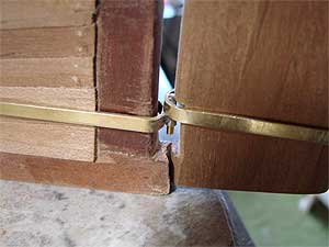
Of course, since I am not planking the ship on the exterior, the gudgeons will be applied to the ribs and transoms. I think I will just temporarily fit them so that they may be removed easily.
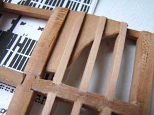
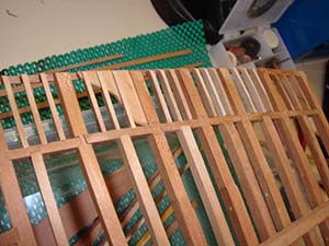
Continuing to fill out the several deck timbers, this image of the Upper Gun Deck shows the latest timbers installed. Note that the new pieces appear much lighter in color than the older cherry wood. That is what aging does to cherry wood.
I have decided to lay on the decking on this Upper Gun Deck, just the port side, enough to demonstrate how it would look. This image shows the jig that I constructed to drill the tree-nail holes at both ends of each timber.
Showing the planking as it appears from beneath the beams of the Upper Deck.
I have not yet added the trunnels to secure the planking on each of the beams. The length of the planks is determined by the location of each beam underlying the planking, as all trunnels need to be firmly bedded in a beam. The spacing of the beams is determined by the plans, and is not necessarily uniform.
You
may want to refer back to this web site as the construction of the HMS
Victory evolves.
I will certainly make every effort to keep this page up to date, but such a project takes years of work, and probably will never actually be completed by me.
Thanks for you consideration and I welcome your comments via email
to: donevans@lazuli.com
The Plans
The plans are for sale by the author, John McKay in BC, Canada, I don’t remember his address, but you can find him on the internet.
However, I found another method of getting the exact same plans in a convenient way:
-
Purchase John McKay’s book ‘The 100-gun Ship Victory’ complete with 1/192 scale fold-out plans (ISBN 1-55750-418-0).
-
Scan the pages you wish to have as plans, 1:1.
-
Using Photoshop CS3 or equivalent software, enlarge by a factor of 4 (for 1/48) or whatever scale you want.
-
Print out in black and white.
Voila’, you have the plans that I have been following!
This has worked out to be an exact 1/48 scale process and has been checked many times to be sure.
With modern scanners/printers, the conversion is exact and can’t be improved upon.
Of course, I have often cropped images to get just the parts I want at the time.
Don Evans